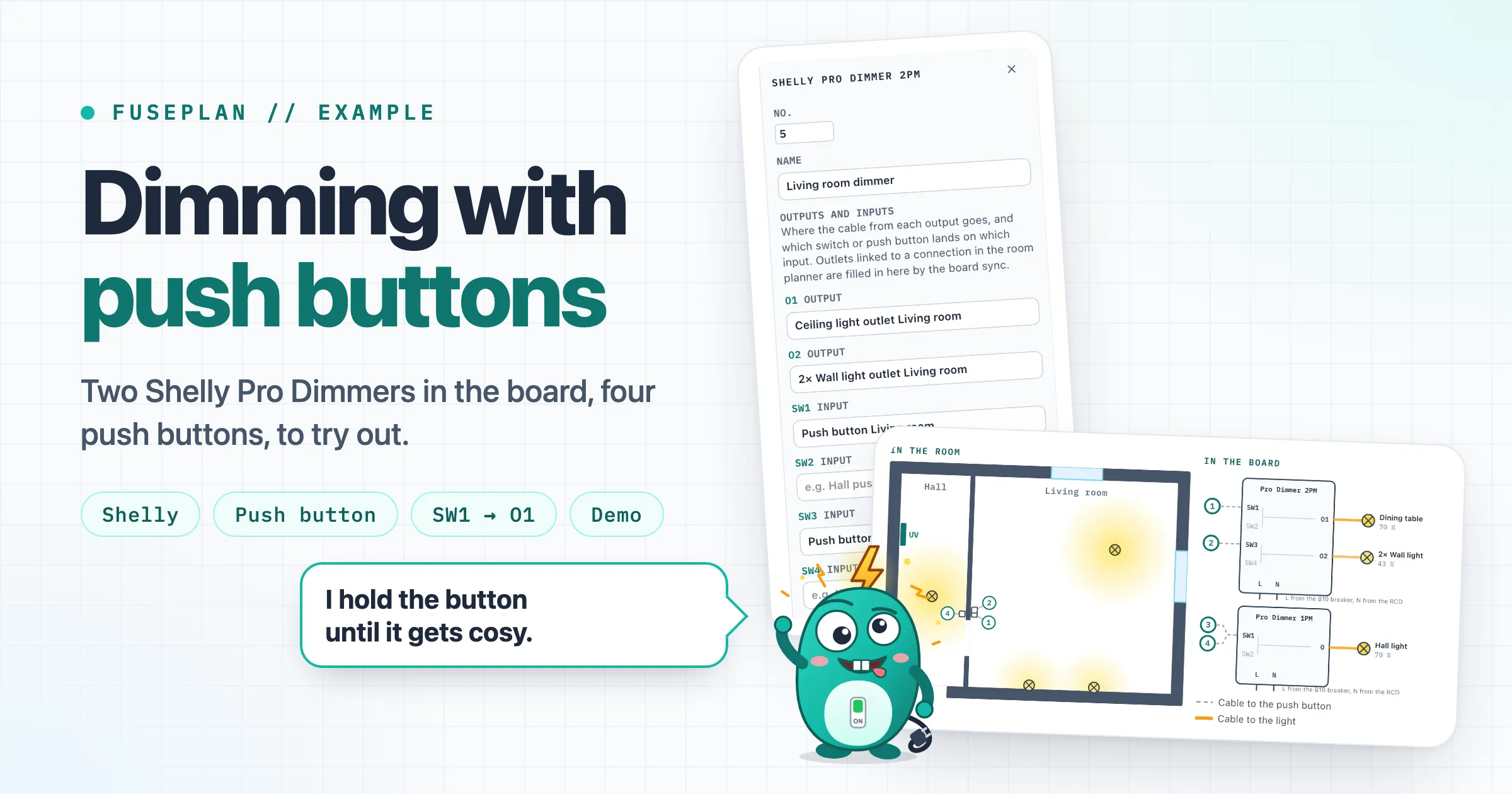
Dimming lights with push buttons and a Shelly Pro Dimmer in the board
Two Shelly Pro Dimmers in the board, four push buttons in a hall and a living room. A small example to try out how buttons, dimmers and lights connect.
The example is a small flat with a hall and a living room. Every light hangs on one of two Shelly Pro Dimmers in the distribution board, and the walls only have push buttons. Press the buttons in the demo below to see what happens in the room and in the board. Behind it is a complete FusePlan project you can open in the room planner and the board planner.
Push buttons instead of switches
A switch latches in its position, and the load current of the light flows through its contact. A push button is a normally open contact that springs back. Its contact is only closed while you press it. In the example it then connects the live conductor to an input of the dimmer in the board, SW1 for example. The dimmer evaluates how long the input sees voltage. A short press switches the output on or off, a long press dims. The load current of the light comes from the dimmer’s output and does not flow through the push button.
So every input and output in use starts a cable of its own in the board. The cable is the same everywhere, NYM-J 3×1.5 mm², or 5×1.5 mm² as a reserve for later. The cables to the push buttons end on an input of the dimmer, the ones to the lights on an output.
Press a button: a short press switches on or off, holding it dims.
In the room
In the board
Nothing pressed yet.
What happens in the board
The Shelly Pro Dimmer 2PM sits on the DIN rail. It has two outputs (O1, O2) and four inputs (SW1 to SW4). SW1 and SW2 control O1, SW3 and SW4 control O2, as Shelly’s knowledge base lists them. With one button per channel, Shelly’s user guide puts the buttons on SW1 and SW3.
In the example, O1 feeds the ceiling light over the dining table and O2 the two wall lights. Button 1 is on SW1, button 2 on SW3. The Shelly Pro Dimmer 1PM for the hall has one output (O) and two inputs (SW1, SW2). Buttons 3 and 4 are both on SW1, wired in parallel, so either of them switches and dims the hall light.
Both dimmers sit behind the B10 circuit breaker of the lighting circuit. The breaker feeds their L terminal, and the neutral (N) comes from the RCD. According to the user guide, the buttons connect to the input and to the live wire. So the cable to a push button carries 230 V, even though no load current flows through it. Among the supported loads, the guide lists dimmable LED and dimmable electronic transformers.
Short press, long press
Shelly calls the mode for one button per channel “dim”. A short press switches the output on or off. A long press dims, each time in the opposite direction to the last one. If the light is off, a long press switches it on and dims up from 0 %. Dimming stops at 100 % or 1 % (Shelly API documentation).
With two buttons per channel there is the mode “dual_dim”. One button dims up and the other down, and a short press on either switches on or off. Both modes require the input to be configured as a button.
Changing the behaviour and programming it
“dim” is one of several modes. With “follow” the output follows the input, with “flip” every change at the input toggles the output, and with “activate” the input only switches on. With “detached” the input does not act on its own output at all. The push button can then trigger something else, for example a light on another Shelly via a webhook (modes).
A push button input tells single, double and triple presses and long presses apart. Each of these events can trigger a webhook (events). For more logic, up to 10 scripts run on the device itself, without a server or the cloud. A script can, for example, set the wall lights to 30 % on a double press. According to the documentation, the Pro Dimmer 2PM also speaks MQTT and has a KNX integration.
The wiring stays the same: push buttons on SW, lights on O. FusePlan plans this wiring; the programming happens in the Shelly app or in the device’s web interface.
Planning it in the room planner and the board planner
In the board planner, place the Shelly next to the breaker of the lighting circuit and connect its L terminal to the breaker. Select the Shelly and the sidebar lists all its terminals under “Outputs and inputs”, each with what is connected to it.
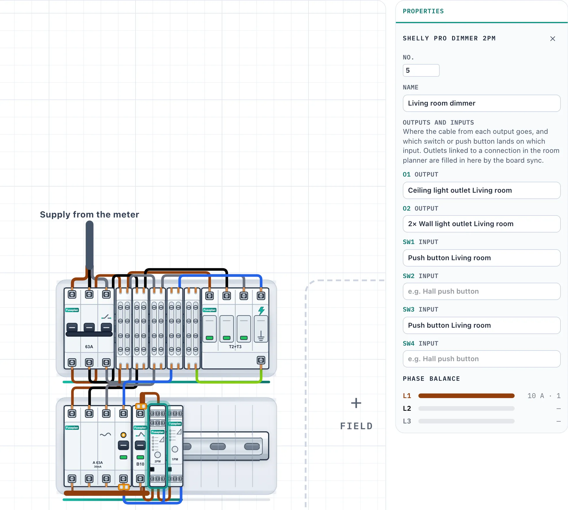
The Shelly Pro Dimmer 2PM in the board planner. The sync named O1, O2, SW1 and SW3 after the outlets; SW2 and SW4 are free.
In the room planner, select a light and set its output in the field “In the board on”, for example O1. For a push button you pick the input, for example SW1. When the planners sync, FusePlan writes the outlet names onto the terminals, in the example “Ceiling light outlet Living room” on O1 and “2× Push button Hall” on SW1 of the 1PM. The names also show in the schematic and in the board’s PDF.
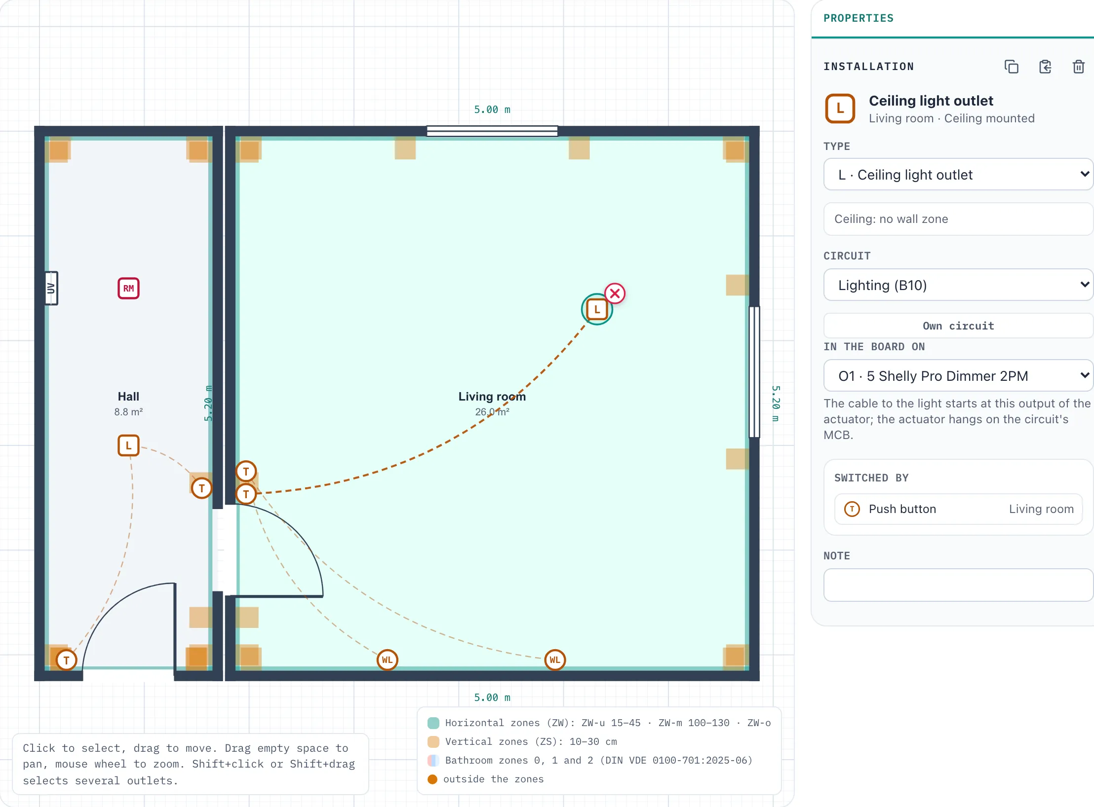
The ceiling light over the dining table is on O1. The dashed line leads to the push button that switches it.
The Wiring tab runs every output and every input as a cable of its own from the board to its outlets. In the example that makes six cables of NYM-J 3×1.5 mm², 67 m in total. If a light hangs on a Shelly that sits behind the breaker of another circuit, the Hints tab lists “Actuator behind another circuit’s MCB”.
The links under the demo open the whole example in the room planner and in the board planner.
Comments
Write a comment